# Keel problems article by Colin Bishop
Reference notes compiled by Colin Bishop - J21 Athene. Sail No:36 - December 2006
A number of Members have recently been experiencing keel related problems with their lift keel J21s. The willingness of other members to share their own experiences and remedies has been a great help in resolving tricky issues and in providing mutual support and encouragement. Nothing is impossible if you know what you are faced with!
These notes are a compilation of comments, help and advice from several different sources and are intended to provide a source of reference for J21 owners. In particular I am indebted to Peter Brookes, John Duff, John Gorringe, Adrian Lumb, David Metcalfe, Stuart Palmer and Roger Somerville plus those members who contributed to the original notes on the JOA Website.
# General view of the Jaguar 21 lifting Keel
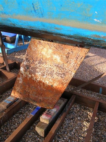
Measurements may include a mixture of Imperial and Metric as both are applicable to these boats.
# Disclaimer
The information and advice given in these notes is intended as a general source of reference only. Not all boats were built exactly the same and many have been subsequently modified. Neither the Jaguar Owner Group as a whole nor any of those responsible for, or mentioned in these notes will assume any liability for action taken by owners as a result of reading these notes. Action taken by owners is entirely their own responsibility or that of agents instructed on their behalf. Keels are large, heavy objects and every possible precaution should be taken when working on them. Likewise, when working on and especially underneath boats, protective headgear, eye protection and masks should be worn appropriate to the task in hand.
# 1. The Jaguar 21 Keel.
In order to tackle problems with the keel it is first necessary to understand how it works. Knowing your enemy is half the battle!
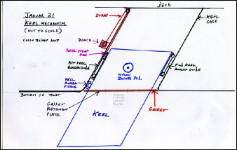
The J21 keel is a conventional arrangement for its time. It's principal features are shown in the diagram and description below.
The keel box is a two part GRP structure which is bolted together on sealant through external lips and bonded to the hull bottom and the deck above. As such it is an integral part of the boat. It also serves as a mast support post. In earlier boats it will be fully encased in wood cladding. The keel box will have circular cutouts for access to parts of the keel when raised but these may vary from boat to boat depending on what work may have been done in the past. In some cases these cutouts may also be taken through the overlying plywood cladding.
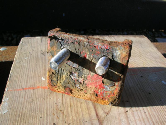
The keel itself is of cast iron and slightly elliptical in cross section. It measures approximately 5 feet long by 2 feet wide and 2.5 inches max in thickness. According to the manual it weighs 550lb (250kg). On the upper fore and aft edges of the keel are bolted two metal channel sections each with two nylon rollers which act as guides when the keel is raised or lowered. The after channel section has a horizontal pin near the top to which the lifting strap attaches.
Near the upper central part of the keel and corresponding with cutouts when in the raised position are two large round nylon bushes, one on each side and bolted together through the keel. These are the stops which, with the heel fitting (described below) are intended to prevent the keel falling through the bottom of the boat when lowered!
There is a single roller heel fitting bolted into the bottom aft vertical external surface of the keel box. This serves as a further stop when the keel is lowered and as a bearing surface during the lowering and raising process. It is also probably intended to support the keel should it strike an obstacle while sailing. The bolts locate into captive nuts in the internal GRP of the keel box.
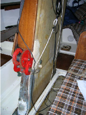
The raising/lowering mechanism consists of a winch bolted to the after part of the keel box just above the waterline which uses a webbing strap to attach to the pin in the upper part of the after channel section on the keel itself. The webbing strap passes over a small diameter roller fitting bolted across the upper aft part of the keel box. Note that, although many boats now seem to have 50mm wide straps, the distance between the retaining lips on many upper roller fittings is 45mm which suggests that this was the width of the originally fitted strap. The 50mm strap appears to work OK but should be checked for scuffing at the sides. It may be possible to modify the upper roller to increase the clearance.
Most boats built since the early 1980s (but not all) should be fitted with a keel retention pin which passes through the keelbox and central part of the keel at about the same level as the winch. This serves to lock the keel up when inserted, thus allowing the strain to be taken off the strap. The pin can also be inserted when the keel is down in which case it passes across the top of the keel preventing it from coming up into the boat.
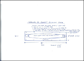
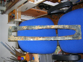
Underneath the boat, around the keel slot, is a moulded recess 36 inches long by 6 inches wide and half an inch or so deep. This accommodates a rubber keel gasket and a GRP retention plate which is screwed into the bottom of the hull. The purpose of the gasket is to help prevent debris being carried up into the keel box when the keel is raised. It also keeps the keel box dark inside which discourages the growth of marine life.
The following diagrams (not to scale) shows the various components :
# 2. The Problems.
With such a simple set up you may well ask what could possibly go wrong? Well, after 20 years or so, quite a bit actually! The main problems faced by members can be summarised as follows:
The strap breaks. Consequences can vary from minor inconvenience to horrendous, including the loss of the keel, depending on the circumstances.
The keel roller fittings corrode resulting in the mechanism seizing.
The winch fails. Effects similar to the strap breaking.
The strap upper roller fitting seizes resulting in premature strap wear.
Leakage around the keel box area. Tricky to get at both internally and externally.
Each topic is dealt with in detail below. But first, a word about working on the keel. Obviously it would be nice if the keel could just be dropped and worked on separately but this is not always possible, especially if your boat is normally stored ashore on a trailer. At the time of writing my boat is in a marina cradle with the keel just about fully down but there is still a couple of feet or so up in the keel box. So, to drop the keel you either need the boat to be temporarily lifted or alternatively the skills of a gravedigger! John Duff has constructed a support frame which facilitates dropping the keel but most owners will not have this sort of facility. Some jobs can be done with the keel in situ, others require it to be dropped.
In order to remove the keel, the two nylon bushes must be removed from the sides of the keel by unbolting/unscrewing through the keel box cutouts, the gasket retention plate and gasket must be removed and the lower aft keel roller fitting removed. John Duff has described the process of lowering of the keel itself as reproduced at the end of these notes. Members who have done this say it needs at least three fit men to manage the lowered keel.
# 1. Broken Strap.
The general cautious view seems to be that the strap should be renewed every three years or if it shows any sign of damage. A new strap is cheap. The consequences of the keel coming loose are not. Two members have lost their keels entirely while another had his crash to the foot of the keel box, breaking the retention plate and possibly straining the structure with the potential for leakage.
One member proposes to use car seat belt webbing as a replacement. Another has sourced a replacement from Lifting and Crane Services at Gloucester (opens new window) for with a certified breaking strain of 2 tons. But be sure that your new strap exactly matches the existing one.
Problems may be experienced with removing the pin on the keel slider plate to refit the new strap. In John Duff's words: The bolt is sure to be rusted in. If you can't get the keel high enough, you may have to jack and block it, I'd measure off where the pin is and cut a hole each side of the keel box with a hole saw about 11/2"D. This will give you access to the slotted head and to the threaded end you may have to drill it out and fit an insert, try to get a hex shaft screw driver which you can hammer into the slot and use a spanner on the shaft, with luck you can shock it loose, use lots of penetrating oil. (an impact screwdriver may also be helpful) The other alterative is to drop the keel and do it on the ground giving you an opportunity to inspect the other rollers and brackets.
Further experiences on renewing the strap are described in the notes on the JOA site which are reproduced at the end of these notes.
# 2. Corrosion of the Roller Fittings.
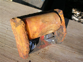
The originals appear to have been made of mild steel and several members have reported complete seizure due to advanced corrosion. To remove the fittings attached to the keel the keel itself has to be completely dropped. It is recommended that replacements are made of stainless steel. Sometimes the old nylon rollers can be reused depending on condition. It is not really possible to judge the state of these fittings without removing the keel except by confirming that the mechanism is still working.
I recently removed the aft roller heel fitting on my boat which appears to be cast iron.. It was very difficult to get out as the bolts were hex headed M10 and I was unable to properly get a spanner on them due to interference with the side of the fitting and the roller. These bolts may not have been original using a as other members have been able to remove the fitting with a socket. Having got the fitting out thin section box spanner I found it to be in surprisingly good condition when cleaned up (my boat is 1983) and intend to refit it. A local metal fabricator will weld M8 nuts onto new M10 bolts to allow me to use a socket or ring spanner to refit.
# 3. Winch Fails
See Adrian Lumb's comments on keeping the friction plate free from grease etc.
# The winch fitted to the Jaguar 21
# 4. The Strap Upper Roller Fitting Seizes
This can result in the strap running out of true and becoming damaged. In David Metcalfe's words: My strap has also been running off centre and rubbing on the winch drum. It was caused by the top retaining bolt being bent and loose. Rather than the roller turning on the spindle the spindle roller had been turning on the bolts. On the port side the bolt had cut an elongated hole in the keel box causing the top roller to slope. I have filled and re-drilled the hole and replaced the bent bolt. The roller now seems to be running correctly and the strap laying on the winch centrally.
# 5. Leakage around the Keel Box area
This can keel box with be very tricky. ANY from below during water round fittings. You as the cure quite drastic - and not yet proven in my case!
The possible sources of leakage are:
The vertical joint between the two halves of the keel box where the original sealant may have partially failed allowing seepage. (May be fore or aft or either)
Seepage through the screw holes which hold the gasket retention plate in place.
Seepage through the bolt holes which secure the aft heel roller fitting.
Seepage through the underside of the hull if the gelcoat has been chipped away under the gasket retention plate and the laminate exposed.
More than one, or all of the above.
These problems need to be tackled from both the outside and the inside on the belt and braces principle. I haven't actually done all of this at the time of writing but it is pretty clear what action is needed.
On the outside, with the boat out of the water and the keel slot accessible, first remove the gasket retention plate and the rubber gasket. This will give access to the affected area. If you can, remove the aft lower keel roller fitting. Generally clean up the area to see what you are dealing with.
First check as far up as you can that the joint between the two sides of the keel box is OK. If in any doubt then fill and fair over with two part epoxy putty which should restore water tightness. Then refit the heel fitting making sure it securely attached and well bedded on waterproof material such as Sikaflex.
Next, clean up and examine the inside of the gasket retention plate recess and make good any chipped gel coat or exposed laminate with epoxy putty. To be absolutely sure you might want to consider adding a thin layer of GRP laminate over the stepped area. (This may entail trimming the retention plate to fit). The gasket retention plate was originally intended to fit flush with the hull using countersunk screws. I'm inclined to think that pan head screws might makei it easier to remove in the future.
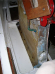
Now to the inside! A local GRP repairer told me that black marks in the laminate are evidence of water penetration. On my boat each of the screws securing the gasket retention plate had penetrated the bottom of the hull and in each case there was a tell talke black mark. This may have been due to the plate having been previously removed and replaced with longer/larger screws. In any event it could well be the source of my seepage problems. How did I check this? Well, that is where if gets a bit difficult! Access to this area is not easy. We had to remove just about all the inside joinery including the sink/galley support, port side half bulkhead, overhead locker and keel side, fore and aft cladding. Actually, most of it came out quite easily, with the exception of the forward keel case cladding which had to be cut across horizontally. All the woodwork is now being refurbished/revarnished at home. Then is was necessary to cut out a section of the port side GRP floor alongside the keel box to gain access to the keel box/hull bottom joint. This was done with a thin cutting disk in a Dremel drill for the horizontal cut and a hacksaw for the end cuts.
What we found was that the screws holding the gasket retention plate were inset about 0.5 inch from the edge of the plate which meant that they screwed into (and through) the bottom of the hull rather than the vertical section of the keel box. The existing holes will be cleaned out and filling in with epoxy putty and a new set drilled 2cm in from the edge to refit the plate.
By now you are probably horrified at what needs to be deon to check this area. However, if your boat is like mine then there is a non damaging way to to do it. Removing the wooden cover alongside the starboard side of the keel box exposes the bilge and concrete ballast. By using a small mirror and a torch you will be able to see if there is a regular series of black spots at approximately 6 inch intervals alongside the bottom of the keel box. If there are then you have probably got seepage on both sides of the keel box and will need to do the full Monty!
With the cladding removed it is also possible to get at the vertical lips used to bolt the two halves of the keel box together and seal any likely looking holes from the inside. In my boat this is difficult due to a previous bodged attempt to cure leaks by plastering GRP cloth and resin around the foot of the keel box fore and aft which has only served to redirect rather than cure leakage and now needs further attention.
# Aft keel fitting & bolts
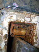
# Forward keel fitting
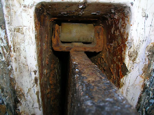
# Heel fitting with captive nut exposed
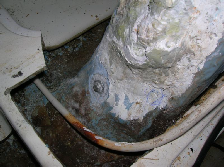
# Gasket plate removed
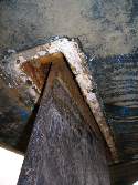
# Gasket retention plate
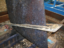
# Keel aft after removing heel roller fitting
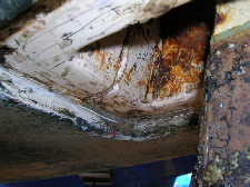
# Aft roller fitting
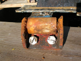
# Aft roller fitting
# Aft roller fitting
# Top of keel
# Keel retention plate
# Refurbished fitting with M8 nuts welded to bolt head
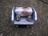 refurbished
# Portside keelbox exposed
